- CNC Precision Machining Parts China Manufacturer and Supplier
- +1 707-684-2707
- +86 130 6186 5801
- [email protected]
CNC Machining Parts Design Guide-Overview
CNC Machining Parts Design Guide-Tolerances
6月 3, 2016CNC Machining Parts Design Guide-Overview
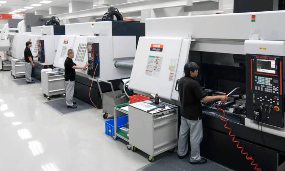
CNC (Computer Numerical Controlled) Machining is a mean to remove materials with high speed, precision machines that use a wide variety of cutting tools to create the final design. The most common used CNC Machines to create shapes designed by customers are: milling machines(vertical and horizontal) and lathes.

Round shapes parts can be manufactured more economically using a CNC lathe versus a 3 or 5-axis CNC milling machine. With a CNC Lathe, turning tools are fixed and the part is turning, whereas on a CNC mill, the tool turns and the stock is fixed. To create the shape, the computer controls the rotational speed of the stock as well as the movement and feed rates of the fixed tools needed to manufacture the part. If square features need to be created on a round part, the part will be created on the CNC lathe at first and then create the square features on the CNC milling machine.
To make parts on CNC Machines, CNC programs instruct the machine how it should move.
The programmed instructions used on the CNC machine are encoded with CAM software in conjunction with the CAD drawing provided by the customer.
Load the CAD model into the CAM software and then tool paths will be created in accord with the required geometry of the manufactured part.
After the tool paths are determined, the CAM software will define the machine about how fast to turn the stock/tool, and the location of moving in axis system.